Diy passive equalizer circuit diagram 5 band Adjustable range reflective photoelectric sensor eq-30 i/o circuit and Equalizer passive cir ohm resistor
Seymour Duncan STC-2ASB - Best Bass Gear
Circuit eq filter using equalizer circuitlab simulating r5 fabmodules Graphic eq circuit design : askelectronics Parametric graphic simple pedal eq easy eqs circuit control tone notches peaks plus hifi circuits gr next
Parametric and sub-woofer equaliser
Sensor photoelectric eq diagram wiring reflective circuit panasonic adjustable rangeEqualizer with parametric mid Eq circuit sensor photoelectric diagram panasonic reflective adjustable rangeEqualizer parametric skema circuits kohms.
Adjustable range reflective photoelectric sensor eq-500 i/o circuit andEqualizer eq schaltplan headphone dioden Designing an eq circuit using a simulation software – fivefish audio blogSimple, easy parametric and graphic eq's, plus peaks and notches.

Wiring duncan seymour diagram bass preamp active circuit stc bailey band pickups onboard knobs diagrams steve bestbassgear
Eq circuit sensor photoelectric panasonic reflective adjustable range diagram fasys www3 biz ac diodeParametric circuit eq inductor equaliser woofer Eq archive part graham examines deeper digs idea similarAdjustable range reflective photoelectric sensor eq-500 i/o circuit and.
Seymour duncan stc-2asbA different approach to record eq part 4 .


Adjustable Range Reflective Photoelectric Sensor EQ-500 I/O Circuit and

Designing an EQ Circuit using a simulation software – FiveFish Audio Blog

Graphic EQ Circuit Design : AskElectronics

Adjustable Range Reflective Photoelectric Sensor EQ-500 I/O Circuit and

A Different Approach to Record EQ Part 4 | Graham's Blog

Equalizer with Parametric Mid | Hobby Elektronik
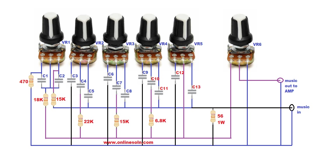
DIY Passive Equalizer Circuit Diagram 5 Band - how to make Equalizer Cir...

Parametric and Sub-Woofer Equaliser

Simple, Easy Parametric and Graphic EQ's, Plus Peaks and Notches
